In version 12.0, the element for the incoming and out-going flows are automatically pulled into sub-diagram when:
- Modeling the behavior of an action in UML Activity Diagram

- Modeling the detail of a submachine state in State Diagram

- Modeling the detail of sub-process in Business Process Diagram

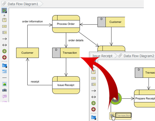
- Decomposing the process in Data Flow Diagram

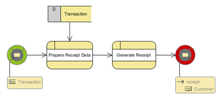
Once the sub-diagram is being created and the incoming and outgoing flow are pulled into the sub-diagram, you can then start modeling the sub-diagram from the incoming flow and end with the out-going flow.
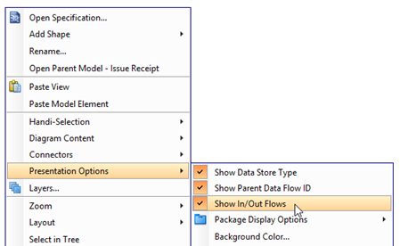
To turn on the in-flow and out-flow indicator, right-click on the blank area of the diagram and select Presentation Options > Show In/Out Flows.
Once the In-flow and Out-flow indicator are shown, you can navigate to the parent diagram by double click on it.