The history of database can be traced back to the earliest days of electronic computing. Over the years, there has been a number of database types emerged, such as hierarchical database, relational database, object database, XML database etc. They differ in hardware requirements, efficiency, and how data is stored, organized and accessed.
Relational databases store data in collections of tables. Relations are defined between tables for cross referencing. The way it stores data makes users easy to understand the structure and content of the data. Developers may use Structured Query Language (SQL) to query data, and add indexes to database for faster querying, making relational database performs well even when the amount of data increases over time. Therefore, despite being challenged by object database for years, relational database still remains to be the most prevalent way of storing enterprise data to this date. Oracle, Microsoft SQL Server, MySQL and PostgreSQL are some of the popular relational database management systems.
How Relational Database Works
Relational database stores data as collections of tables. Each table contributes a set of columns, which are the properties of the table that are worthwhile and need to make persist. Relationships, critical elements in relational database can be added between tables to indicate that two sets of data are inter-related.
Table
A relational database consists of a collection of tables (i.e. entities), from which we want to seek information. A table consists of columns, which are the properties of the table, and rows which are the records to store and retrieve.
Column
Columns refer to a set of fields in tables. A column describes a property we are interested in storing for the table it belongs to.
Relationship
A relationship is a connection between two entities. It connects data (in tables) together in meaningful ways. For instance, knowing the information of a transaction is meaningless without knowing the customer who performed the transaction. Hence, we would relate the customer and transaction tables to obtain complete information about a transaction.
Example: School
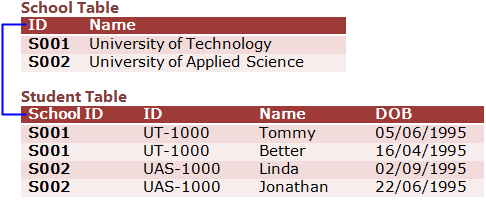
An entity relationship diagram (ERD) is a visual form of relational databases. People use ERDs to model and design relational databases. The following is an ERD that depicts the tables for a simple school system.
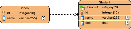
School and Student are entities (note: In ERD, the term "entity" is often used instead of "table". They are actually the same). In the School table, there are two columns - id and name. id is the primary key (PK) column, which is in bold and has a key symbol next to it. A primary key is capable in uniquely defining records in a table. In other words, there must not be two (or more) school records that share the same id. Student, another table, has a foreign key column, namely SchoolId. It is a reference to the primary key Id in the School table. Note that foreign keys need not be unique. Multiple student records can share the same School ID. In a real world scenario, there can be multiple students studying at the same school and therefore have the same school id.
Between the School and Student entities, there is a connector. We call it a relationship. In this case, it is a one-to-many relationship. It means that the entity with the primary key (i.e. School) contains only one record that associates with zero, one or many records in the referenced entity (i.e. Student). We can describe the relationship in everyday language by saying: A school intakes many students.
Relational Database Design with ERD
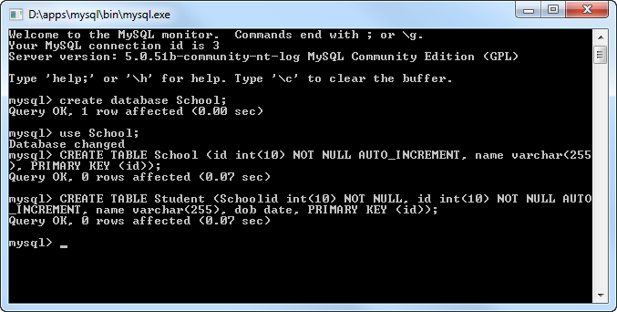
If the database you are going to build consists of a few tables only, you do not need to design it at all. You can simply use the management tools provided by the database management system, or run a few SQL statements to get the database built. However, this would hardly be the case in real world.
If you are planning a database with more than 10 tables, or even up to hundreds of tables, it would be better to consider designing the database prior to building it. Here are some of the benefits of database design:
- It provides a means for you to study the data structure, to make sure necessary tables and relationships are well included. In addition, well-designed database leads to efficient data addition and retrieval.
- During the design process, you can understand not only the data structure but also the target system can be better. This helps your team to develop the rest of the system.
- Assume you have recently developed a system. Three years later your client has updated the business plans and strategies and request you to upgrade the existing database to fulfill the new requirements. It would be a pain to plan and execute changes by looking into the database to study the table definitions. Database design always gives you a clear picture of what you have done.
- Database design is not just for you. It also allows your clients to review and comment on your work. It would not be likely that the clients have the technical knowledge to understand exactly how the database works. But a high-level visual design can help them to see if your design meets their needs or not.
Drawing ERD with Visual Paradigm
A good database design does take time and effort to develop and conceive. A helpful database design software can help you to reduce time and effort spent. Visual Paradigm provides you not only with an ERD tool but also a set of visual modeling features that helps you to express your design ideas more easily and quickly. It supports most of the popular relational database management systems in the market today. Here is a list of supported databases:
|
|
In this section, we are going to design a relational database for a bus route management system, using ERD, in Visual Paradigm.
To begin, we need to make decisions regarding what entities to be created. During the process, you may find many candidates. Here are some of the guidelines to help you to identify entities:
- An entity must be a noun (e.g. Transaction) or a noun phrase (e.g. PurchaseOrder)
- Only accept nouns that are meaningful to the system ("Passenger" is disqualified because the bus route management system does not record any information about passenger)
- Only accept nouns that have properties to store ("Fare" is disqualified because it does not have any meaningful properties to store. However, "Fare" could be a column of a potential entity "Route")
Finally, the following entities are obtained:
- Bus
- Schedule
- Route
- Driver
- Stop (which is a bus stop)
Now, let's start the design process.
- Create a new project in Visual Paradigm by selecting Project > New from the toolbar. In the New Project window, name the project Bus Route Management System and click Create Blank Project at the bottom.
- To create an ERD, select Diagram > New from the toolbar. In the New Diagram window, select Entity Relationship Diagram and click Next. Enter First Draft as diagram name and click OK.
- Select Entity from the Diagram Toolbar.

- Click on the diagram to create an entity. Enter Bus as the name of the entity. Note that we usually use singular naming for entity, no matter how many instances the entity may have in real world.
- Press Enter. This gives you the first entity.

- Create the other entities to create a diagram like this:

Now, we can specify the columns for the entities. Similar to identifying entity, you need to think carefully what columns you need to store in each entity. Do not add columns for data that have no value to the system.
- Right-click on the entity Bus to select New Column from the popup menu.

-
Add a primary key column by entering + vehicle_id : integer(10) and press Enter. A plus character is used to specify the primary key column. You don't need it if you want to add a non-primary key column. (Note: vehicle_id is the name of the column.)
Press Esc to stop creating new columns.
-
Add columns to the other entities:
Entity Columns Schedule + schedule_id : integer (10)
departure : date
arrival : dateRoute + route_id : integer (10)
fare : float (10)Stop + stop_id : integer (10)
name : varchar(255)
terminus : blobDriver + driver_id : integer (10)
name : varchar(255)
employ_date : date
Up to now, the diagram should look like this:
- Let's relate the entities. Think about the Route and Schedule entities. A route has many schedules, and a schedule must be under a specific route. Hence, create a one-to-many relationship from Route to Schedule. Place the mouse pointer over the Route entity. Press on the Resource Catalog icon and drag towards the Schedule entity.

-
Release the mouse button over Schedule. Then, select One-to-Many Relationship in Resource Catalog.

When you are prompted to define a foreign key mapping, keep the default settings and click OK to continue.
A one-to-many relationship is created between Route and Schedule:
-
A schedule is handled by a bus, and a bus can handle multiple schedules throughout a day. Hence, create a many-to-one relationship from Schedule to Bus. This time, drag the Resource Catalog icon from entity Schedule to Bus and select Many-to-One -> Entity from Resource Catalog to create a connection.

Up to now, the diagram should look like this:
- Now comes Bus and Driver. A driver drives a bus and a bus is driven by one driver. Create a one-to-one relationship from Bus to Driver. Again, confirm the foreign key creation with the default settings.

- For Route and Stop, a route consists of many bus stops, while a bus stop is shared by many routes. Hence, there is a many-to-many relationship between the. Try to relate Route and Stop with a many-to-many relationship, the relationship is automatically split into two one-to-many relationships, with a linked entity Route_Stop produced in between. This is the final ERD:

