Comparing Logical and Physical ERD
Entity relationship diagram (ERD) represents a detailed picture of the entities needed for a business. In forward engineering, ERD will be transformed into a relational database eventually. There are at least two types of ERD - Logical and Physical. They are used in different stages of development, and are inter-related.
A logical ERD models information gathered from business requirements. The entities and relationships modeled in such an ERD are defined around the business's needs. The need to satisfy the database design is not yet considered.
A physical ERD represents the actual design of the database. It deals with the conversion from a logical design into a schema-level design that will be transformed into a relational database. When modeling a physical ERD, the logical ERD is treated as the base, and refinement occurs by defining primary keys, foreign keys, and constraints. Sometimes, relationships need to be resolved by introducing additional tables, such as a linked table for a many-to-many relationship.
Since the physical ERD and logical ERD represent the business requirement and database schema, respectively, comparing the physical and logical ERDs helps to identify the differences between them, thus confirming that the database is exactly following the initial business requirements, regardless of any changes.
Visual Paradigm's Model Transitor enables you to transition a logical ERD to a physical ERD while maintaining the transition relationship. In this tutorial, we'll see how to use the Model Transitor to transcribe a logical ERD into a physical ERD. After that, we will use Visual Diff, a tool for comparing changes between diagrams, to trace the differences between them.
To complete this tutorial, you must have Visual Paradigm installed. You also need to have a basic knowledge of database design and data modeling with Visual Paradigm.
Create a Project for This Tutorial
To avoid messing up your production data, we will create a new project for this tutorial. In this section, you will create such a project.
- Select Project > New from the toolbar.
- Enter ERD Sample as the project name.

- Click Create Blank Project to confirm the creation.
Drawing a Simple Logical ERD
In this section, we will draw a simple logical ERD that contains just two entities.
- Select Diagram > New from the toolbar.
- In the New Diagram window, select Entity Relationship Diagram and click Next.

- Enter Logical ERD as the diagram name.

- Let's put the ERD to be created in a model for better grouping. Click ... next to Location.
- In the Select Parent Model window, click New Model.
- In the Model Specification window, enter Logical Model as the name and click OK.

- Click OK in the Select Parent Model window.
- Click OK to confirm the creation of the Entity Relationship Diagram. On the right-hand side of the diagram, you should see a floating panel called Data Model, with the option Logical Model selected. If you find that Physical Model is selected, it's possible that you have entered the wrong name in step 6. If that's the case, select Logical Model manually now.

- Click on the background of the diagram. The Data Model panel will then disappear.
- Draw two entities, Customer and Order, in the ERD.

-
Add the following columns to the Customer entity:
Column name : varchar(255) address : varchar(255) order count : integer (10) 
-
Add the following columns to the Order entity:
Column amount : integer (10) date : date 
That's all for our logical ERD. Since it aims to represent business requirements, it's quite simple, and as you can see, we haven't added any keys yet.
From Logical ERD to Physical ERD
In this section, we will form a physical ERD from the logical ERD we drew in the previous section.
- Right-click on the background of the logical ERD and select Utilities > Transit to Physical ERD... from the popup menu.
- This time, let's group the diagram to be created in a model named Physical Model. In the Select Parent Model, click on the project root node first.

- Click New Model.
- In the Model Specification window, enter Physical Model as the name and click OK.

- Keep Physical Model selected in the Select Parent Model window and click OK.
-
You should see a new ERD formed, which looks quite similar to the logical ERD, except that the entities are in orange and have a primary key column automatically created.

Now, let's modify it to make the diagram a real physical ERD.
- First, one Customer can have multiple Orders. Let's connect them with a one-to-many relationship. Click OK when prompted for the creation of a foreign key column.

- The order_count column is redundant because the number of orders can be obtained by counting the number of Order records associated with a particular customer. Let's delete this column. Select it and press Delete.

- "Order" is a reserved word that cannot be used as a table name. Let's rename the Order entity to Purchase_Order.

Comparing a Logical and Physical ERD with Visual Diff
Let's compare the two ERDs. Doing so allows us to see the differences between the logical model and the physical model.
- Let's open the logical ERD. To do so, click on Switch Diagram on the navigation bar and then double-click on the logical ERD to open it.

- Select Modeling > Visual Diff from the toolbar.
-
Select the physical ERD on the right-hand side of the Visual Diff window.

- Top: Settings for controlling how and what to compare.
- Left-hand side: A list of diagrams in the two projects selected on the left and right-hand sides.
- Middle: A pane that has two sides. Each side represents a project and one of its diagrams. A comparison is made for the two sides.
- Bottom: The differences between the two diagrams are shown here.
-
At the top left corner of the Visual Diff window, select Transitor as the comparison strategy.

There are three types of strategies:- ID: Shapes will be matched based on their internal model element ID. This type of comparison is useful for visualizing differences between different stages of a design.
- Name: Shapes will be matched based on their names. This type of comparison is useful for visualizing differences in external works. Typical examples include comparing databases and class models.
- Transitor: Shapes will be matched based on their transition established by the Model Transitor. This type of comparison is useful for visualizing differences between different models.
- Next to the Strategy setting, there is a drop-down menu for selecting what to compare. For View, differences like the coordinates of a shape will be reported. For Model Element, differences such as the name of a model element or other specification-level changes will be reported. Since we are only interested in knowing the differences at the schema level, select Model Element.

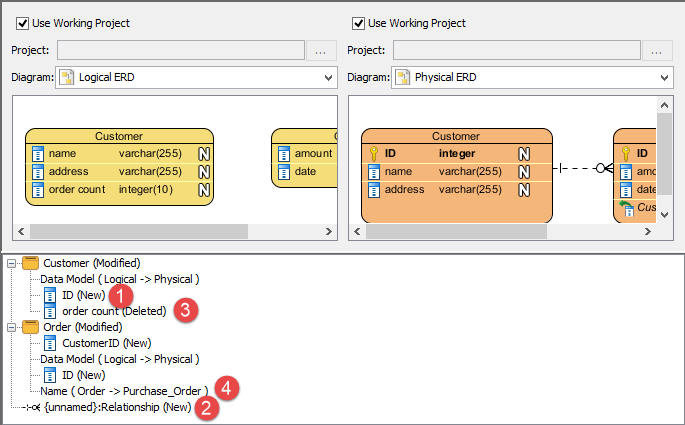
- Check the results. The differences between the logical and physical ERDs can now be easily found.
- The ID column has been added in the physical ERD.
- The one-to-many relationship has been added.
- The order_count column has been deleted.
- The Order entity has been renamed to Purchase_Order.