Introduction to BPMN Part III - Flow and Connecting Objects
In BPMN, flow elements are the individual components that are connected together to form a complete process flow. These flow elements are connected using connectors, which are known as connecting objects. When reading a Business Process Diagram (BPD), readers follow the flow of these elements to understand how a business process is executed and completed.
BPMN includes four types of flow elements: Activities (Task and Sub-Process), Events, and Gateways. In contrast, there are two main types of connecting objects: Sequence Flows and Message Flows.
Activities
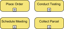
Activities represent the work performed within a business process and are depicted as rounded rectangles with names that describe the work to be done. There are two types of activities: Task and Sub-Process. A task is used to model an atomic unit of work that cannot be broken down further or does not make sense to do so.
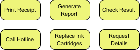
On the other hand, when you want to model a non-atomic, complex piece of work that can be broken down into smaller tasks, you use a sub-process. A sub-process can be broken down into another level of detail, which is why a sub-process usually contains another BPD that models its details.
Note that the choice between a task and a sub-process is not just about the complexity of the work, but also about the level of detail you need to know. For example, if you are a customer, you probably don't need to know how your payment is being processed. However, if you are the shop owner, the details of how a customer's payment is processed are very important.
Events
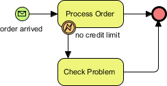
Events represent occurrences that can affect a business process and can be either internal or external. They are shown as circles with icons to indicate the type of trigger. There are three types of events: Start, Intermediate, and End. Each event can have a specified trigger condition. A start event shows where the process begins, while an end event indicates where it ends. Intermediate events can drive the flow of a business process based on their specified trigger condition and can be attached to an activity or connected by a connecting object to model events that may happen during or after an activity. For example, in the given diagram, the process starts when an order is received and ends when the order is processed or a problem is identified, which happens if there is no remaining credit limit.
Gateways
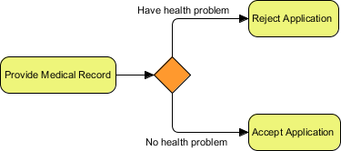
Gateways, shown as diamond shapes, control the flow of a business process by making decisions based on internal or external conditions. For example, a discount may only be offered to a VIP buyer. There are several types of gateways, including:
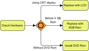
Data-Based Exclusive Gateway: Controls the process flow based on given process data. Each outgoing flow corresponds to a condition, and only one flow is taken based on the satisfied condition.
Inclusive Gateway: Creates parallel paths where all outgoing flows with positive results are taken, resulting in the execution of multiple flows if multiple conditions are satisfied.
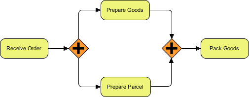
Parallel Gateway: Models the execution of parallel flows without checking any conditions, meaning all outgoing flows are executed at the same time.
Event-Based Gateway: Models alternative paths based on events. For example, waiting for a "Yes" or "No" reply to determine which path to take. The gateway is followed by two connected intermediate events with message triggers, with one representing "Yes" and the other representing "No." When one of the events is triggered, the flow that follows that event is taken, and all other events and their subsequent flows become invalid.

Sequence Flows
A sequence flow is used to connect flow elements. It is shown as a solid line with an arrowhead and indicates the order of the flow elements.
You can only use a sequence flow to connect flow elements within the same pool, either within the same lane or across lanes in the same pool. If you want to connect elements across different pools, you must use a message flow instead.
Message Flows
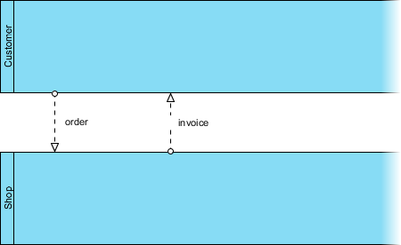
In BPMN, communication between pools is achieved through messages. A message flow is used to show the flow of messages between pools or between flow elements in different pools. A message flow is shown as a dotted line with an arrowhead. Some examples of messages that flow between pools include faxes, telephone calls, emails, letters, notices, and commands.
Case Study: The True Aqua Distilled Water Company (Continued)
In Part II of this tutorial, you started drawing a BPD for The True Aqua Distilled Water Company, creating several pools and lanes. Now, we will draw the process flow. If you missed Part II, you can open it by clicking the hyperlink at the bottom of this page.
- Based on the process description from the distilled water company, we know that the process starts when a customer places an order for distilled water. Therefore, create a start event in the Customer pool to indicate the beginning of the process. Select Start Event from the Diagram Toolbar.

- Click in the Customer pool.

- Create a task after the start event for placing the order. Move the mouse pointer over the start event, then click and drag the Resource Catalog icon (at the top right) to the right.

- Release the mouse button and select Task from the Resource Catalog.

- Enter Place Order as the name and press Enter to confirm. This will create a task named Place Order.

- The customer service assistant who receives the order needs to verify the customer's identity. Create a task for this activity. Note that the task should be placed inside the Customer Service Assistant lane. Click and drag the Resource Catalog icon downwards.

- Release the mouse button in the Customer Service Assistant lane. Select Task from the Resource Catalog and name the task Verify Customer Identity. Note that a message flow is automatically created between Place Order and Verify Customer Identity instead of a sequence flow because they are in two different pools.

- If the customer has never placed an order before, the customer service assistant will create an account for them. Otherwise, they will forward the order to the Logistics Department on the following Wednesday. To model these two possible flows (for a new or existing customer), we need to use a gateway. Use the Resource Catalog to create a gateway from Verify Customer Identity.

- Name the gateway Customer Exist?.

- If the customer record does not exist, an account needs to be created. Let's model this flow. Create a task from the gateway using the Resource Catalog.

- Name the task Create Customer Account and name the sequence flow No. This means that if the condition is not met, this flow will be taken, and the task Create Customer Account will be performed.

- What if the customer record already exists? The customer service assistant will forward their order on the following Wednesday. To model the need to wait until Wednesday, we will use an intermediate event. Use the Resource Catalog to create an intermediate event from the gateway.

- Name the intermediate event On Next Wednesday and name the sequence flow Yes.

- The intermediate event will be triggered at a designated day/time, so it is a timer event. To represent this, right-click on the event and select Trigger > Timer Trigger from the popup menu.

- The order will be forwarded to the Logistics Department on the following Wednesday. To represent this, create a task named Forward Order after the intermediate event. Use the Resource Catalog to create a task from the event.

- Name the task Forward Order.

- Don't forget the activity to perform after creating a customer account. After the customer service assistant has created an account for a new customer, the order will also be forwarded on the next Wednesday. Therefore, you need to add a sequence flow from Create Customer Account to the intermediate event On Next Wednesday. Do NOT connect it directly to Forward Order, as this would skip the wait until Wednesday. Again, you can use the resource icon to create a connection from Create Customer Account. This time, release the mouse button inside the intermediate event to add the connector.

- The water delivery order will be forwarded to the manager in the Logistics Department to arrange for delivery. Use the Resource Catalog to create a task in the Manager lane from Forward Order.

- Name the task Arrange Delivery.

- The activity of arranging delivery actually involves several sub-activities. Is it more appropriate to model it as a sub-process instead of a task? The answer is yes. But what should you do now? Delete the task and create a sub-process? You don't need to delete the task. Instead, you can convert it into a sub-process. Let's try this by right-clicking on the Arrange Delivery task and selecting Convert to Sub-Process from the popup menu.

- A sub-process contains another BPD where you can draw its details. The plus sign allows you to drill down to the sub-process by opening the BPD. Click the plus sign on the Arrange Delivery sub-process and select New Business Process Diagram from the drop-down menu.

- This opens a blank BPD. You will see a pair of start and end events. These are used to connect the main flow modeled in the parent diagram and the sub-process flow to be modeled in this diagram. Apply the techniques you have learned above to create three tasks—Assign Workers, Print Schedule, and Post Schedule—between the two events.

Note that in some cases, you may want to present the previously created pools and lanes in the sub-process diagram. To do this, right-click on the background of the BPD and select Add Pools/Lanes from Parent Diagram... from the popup menu. In the Select Pools/Lanes window, select the Manager lane and click OK. - Let's go back to the parent BPD. Click on the shortcut link at the top of the diagram.

- The sub-process is in a collapsed state. You can optionally show its content by clicking the + icon at the bottom of the shape. This will show a thumbnail of the sub-process BPD inside the sub-process shape. If you resize the sub-process, the thumbnail will resize as well. However, we do not recommend showing the content of the sub-process BPD here. Firstly, because of the complexity of the parent diagram. Secondly, when you use a sub-process, it implies different levels of process detail. If the detail is so important that you must show it in the parent diagram, you should probably reconsider whether to model the "sub-flows" directly in the parent BPD rather than using a sub-process BPD. Therefore, we recommend keeping the sub-process collapsed here.

- After arranging delivery, the workers will be responsible for the delivery. Create a task named Deliver Water after Arrange Delivery in the Worker lane (the bottom lane).

- This is almost the end of the water delivery process. Just as we did in the sub-process BPD, create an end event here to indicate the end of the process. Use the Resource Catalog to create an end event from Deliver Water.

- Finally, you should have a BPD that looks similar to this:
